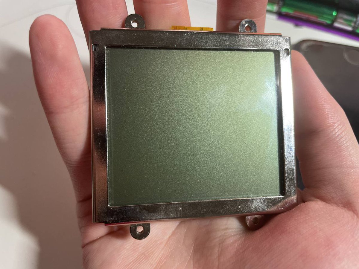
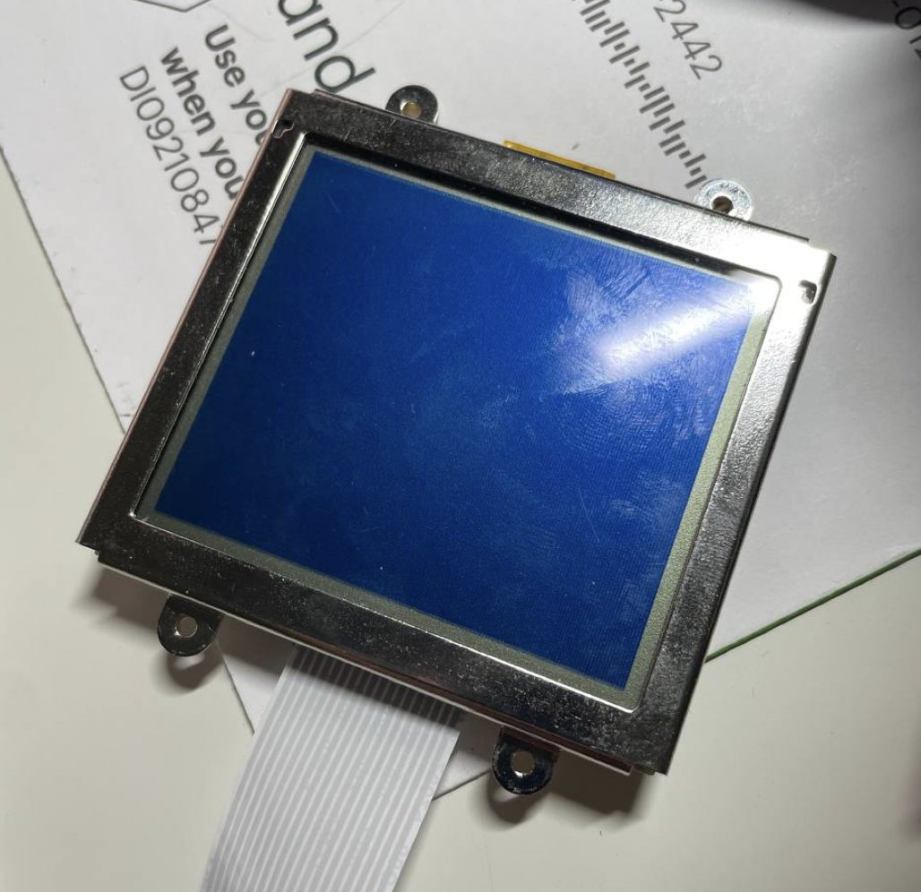
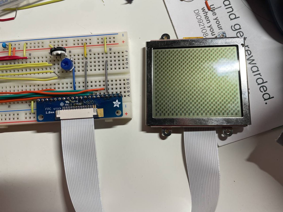
Quick weekend project: I have many LCD modules in my drawer. When I am feeling stressed out/ burnt out, I would just randomly pick one from the drawer and try to make it work. So, today I have got this small LCD module, with no datasheet or any documentation:
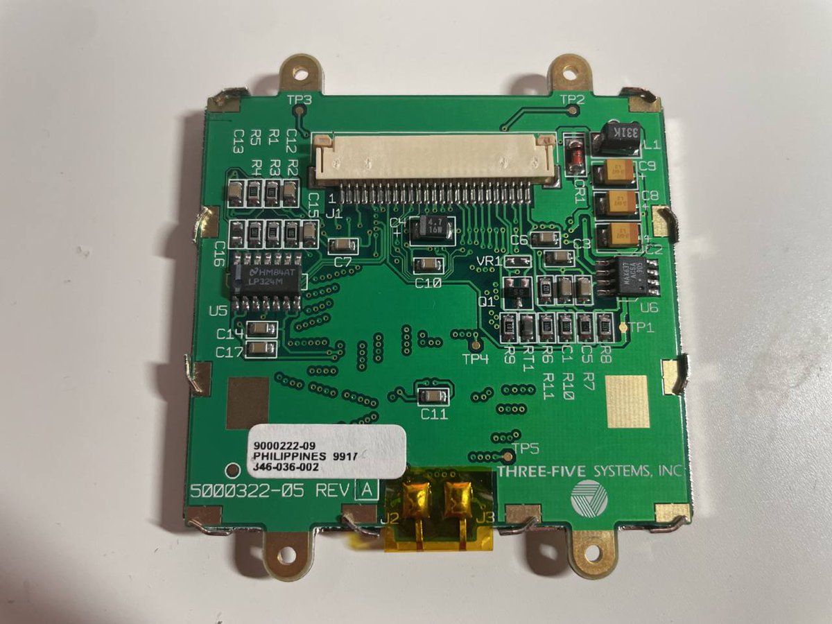
The backside of it, no identifiable LCD controller or driver chip. The connector has 25 pins. Searching the model number showed me that the manufacturer has gone bankrupt more than a decade ago, and it's being used on some data terminals, with a resolution of 160x128.
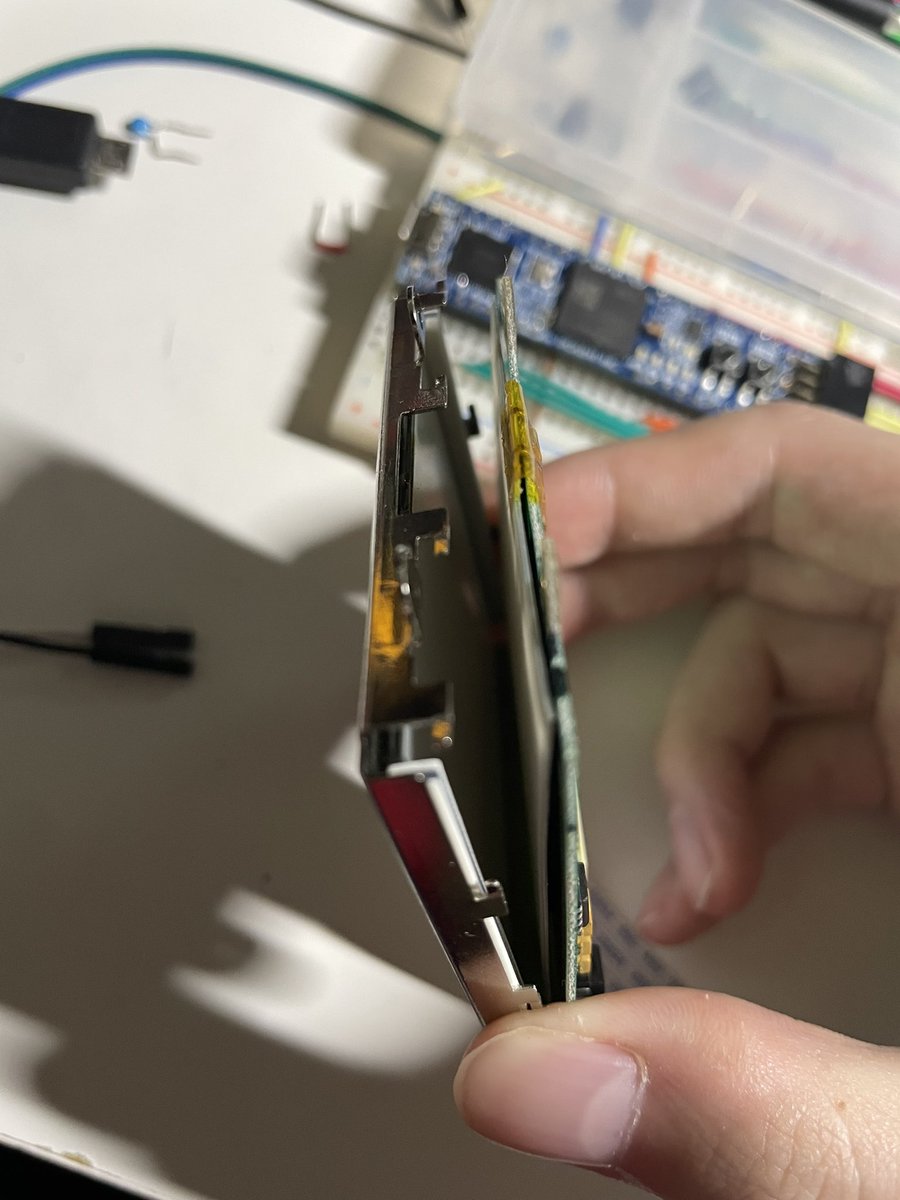
It’s a bit hard to take it apart without breaking it due to the construction so I am not doing it. But just peeking through the side, it looks like it has got 3 COB chips for driving the screen.
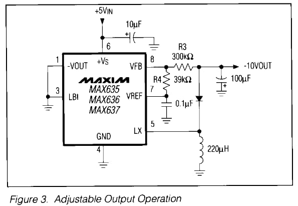
Back to what's visible on the back of the screen. An 324 opamp and an HV637 inverting DC-DC converter. These two form a classic LCD bias voltage generation circuit. The DCDC generates a -10V to -20V voltage, with a bunch of resistor voltage dividers, followed by opamp follower.
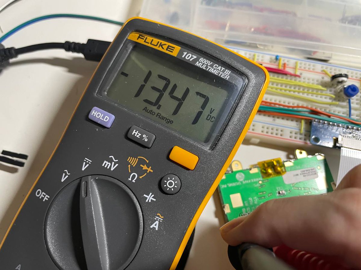
Then I can probe and see which pins are power supply rails. Turns out pin 5, 6, 8, 14, 15, 23, and 25 are all ground connections, and 13 is 5V supply input. If I just connect the power pins, I get this. By measuring the voltage, seems like the DCDC is not working yet.
Turns out by default, the voltage feedback loop is not closed. It's up to me to do that. So it allows me to control the contrast using some pins. Though the resistor configuration doesn't make much sense to me, and seems like there are 4 or 5 pins for that.
Not interested in understanding how the voltage generation circuits works (at least not yet, I don't want to spend too much time on it when I don't even know if I can map out the signals), I decided to simply short some resistors and close the loop myself with a potentiometer.
Now on to the real question: how to control it. First I need to know if this screen is a self-refresh one or not. If so, it would have some sort of controller like KS0108 and uses something like M68 bus interface. Then I will need to find out the controller model to talk to it.
Or if it’s not a self refresh one, I will just need to supply the HV sync signal to it and it should just work! And I have got some clue: when I touch it, it flickers. It looks like 60Hz AC signal is coupled on to some pins. This suggests the screen uses external sync signals.
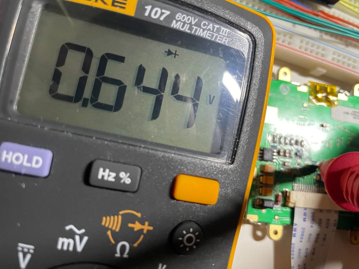
But how do I know which pin correspond to which signal? Here comes the trick, if the wire is connected to some chip's IO pad, and you measure the pin with diode test mode on a multimeter, you will see a diode with ~0.3V - 0.8V drop from GND to the pin
If it's out of the range, then it's not a signal pin. So easily now I can see pin 9, 10, 11, 12, 17, 18, 19, and 20 are signal pins. All with a voltage drop between 0.63V to 0.67V
Okay cool, but which is which? If I try all permutations, that's 8!=40320 possibilities. If I do some educated guess, say that one group must be data bus, so I only need to guess inside 4 control pins, that reduces possibilities down to 2*4!=48. Manageable, but I can do better!
There are 3 driver chips. I would guess 2 of them are segment driver, and 1 is column driver. I have 4 signals needs to be mapped out, Hsync, Vsync, pixel clock, and polarity inversion. Pixel clock only goes into segment driver, Vsync only goes into column driver, rest go into both.
Diode tests mode comes into rescue again. If a wire is connected to multiple chips, that means multiple diodes are connected in parallel. So if the voltage drop is lower, it's connected to more chips. Pin 9 is 0.666V, pin 10 and 12 are 0.639V, and pin 11, 17-20 are 0.658V.
And what do I expect? I expect 4 data pins + clock goes only into 2 chips, Vsync pin only into 1 chip, Hsync and PInv go into all 3 chips. This exactly matches what I measured! Now I know pin 9 is Vsync, pin 11 is pixel clk, 17-20 are data pins, 10, 12 not sure, 2 possibilities to try.
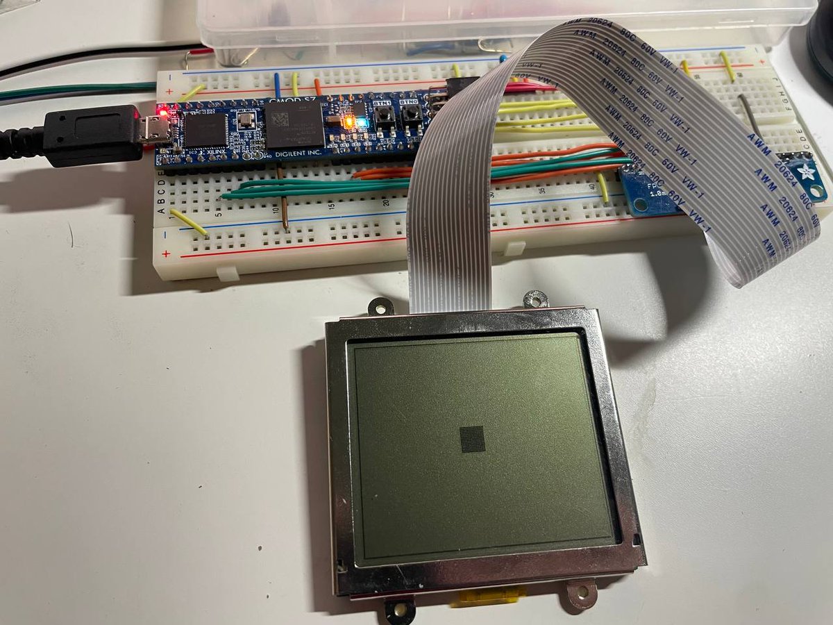
Only way to tell if it's true is to test it. Normally I love use RP2040 for these stuff, but I accidentally killed my Pico before, and digikey still hasn't shipped my Pico W after like 2 months? I guess I will use Cmod S7 (which is the only breadboard-able board I have right now)
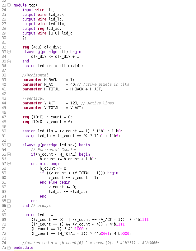
And guess what, it just works! All the guess (or analysis) are correct!
Though I made some mistake in the pin constraints so it's missing some pixel, and the sync signal isn't quite right so the image is shifted. After all these are fixed, I think it's solid now.
That's it for today, thanks for reading, have a nice weekend!