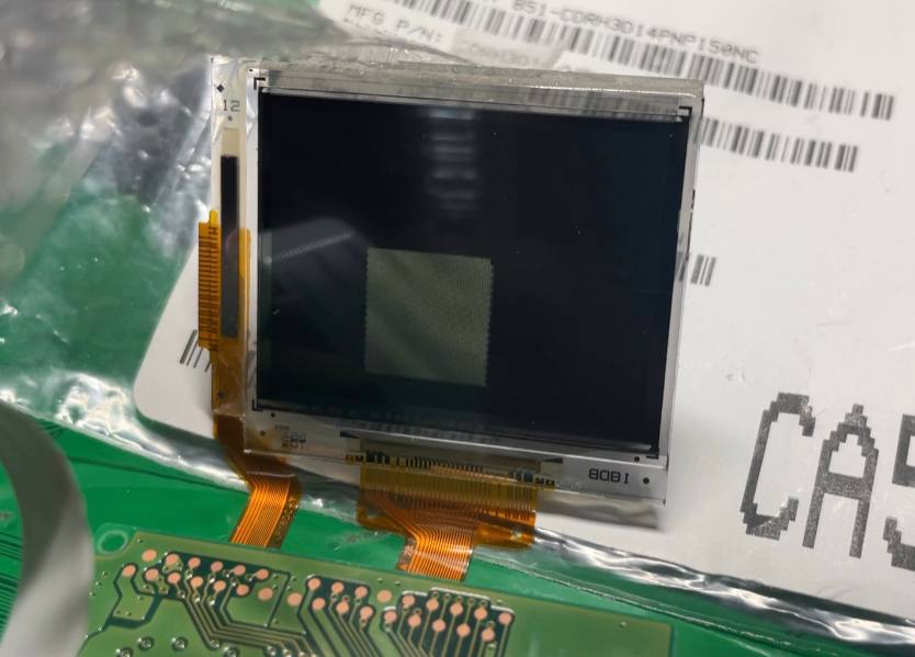
You've probably heard of TFT (Thin Film Transistor) LCDs before, they are pretty much everywhere. But have you heard of TFD (Thin Film Diode) LCDs? Today let's look at one such display: A 1.8" 312x230 TFD color LCD module by EPSON, and drive it with Raspberry Pi RP2040.
TFD is an extinct technology first developed by EPSON to provide a low-cost alternative to TFT LCDs with comparable image quality. As the name suggests, a diode is used in place of a transistor. The external driving circuitry is more similar to passive matrix screens than TFTs.
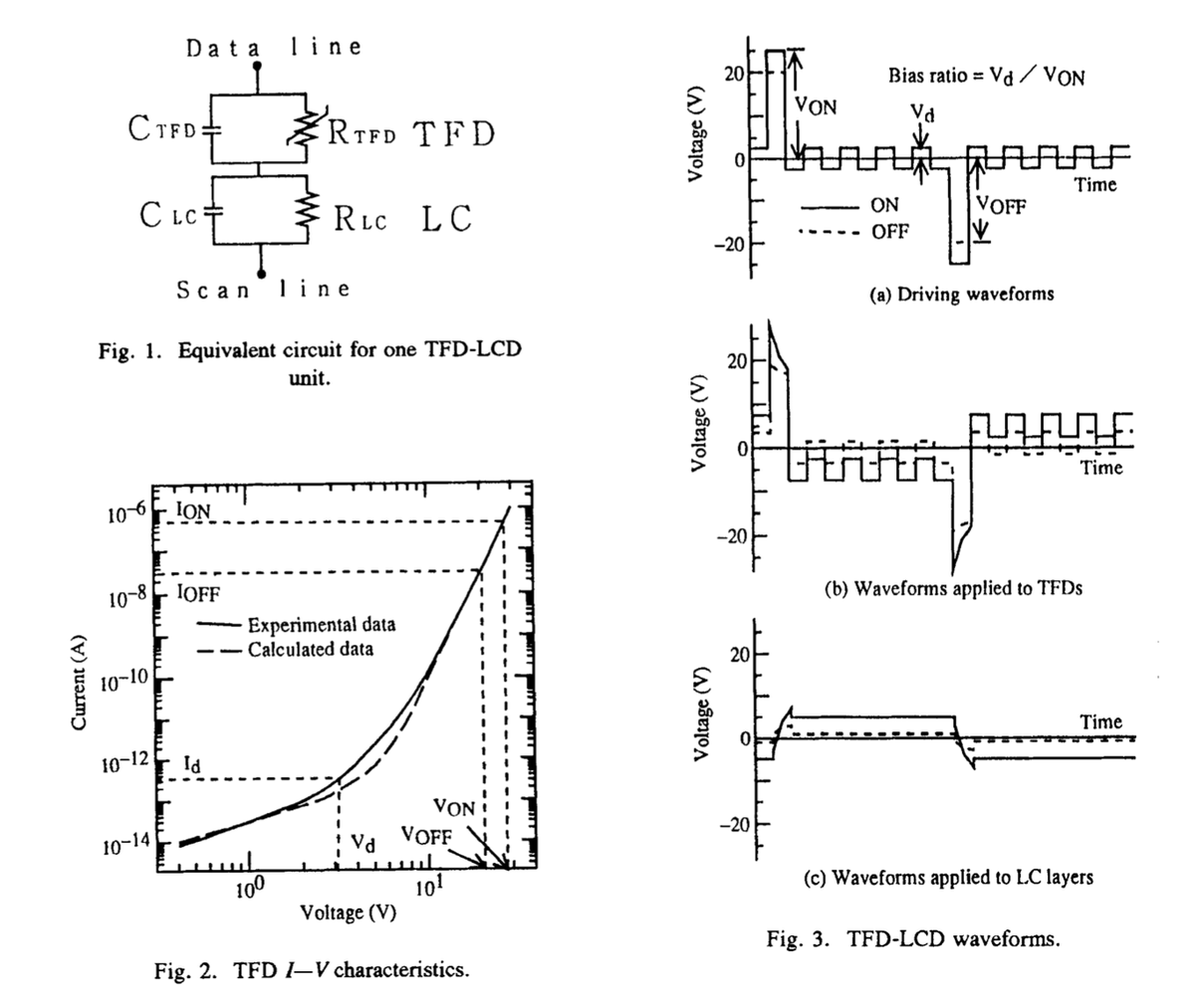
It uses the same driving waveform as passive matrix LCDs (figures from paper Mizobata, E., Hirai, Y., Shimizu, K., Uchida, H. and Kaneko, S. (1994), Design of high-quality TFD-LCDS. Electron. Comm. Jpn. Pt. II, 77: 56-64.). I imagine they could reuse some CSTN driver chips here.
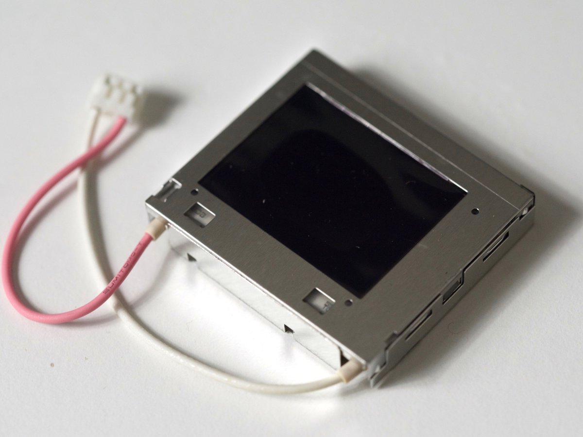
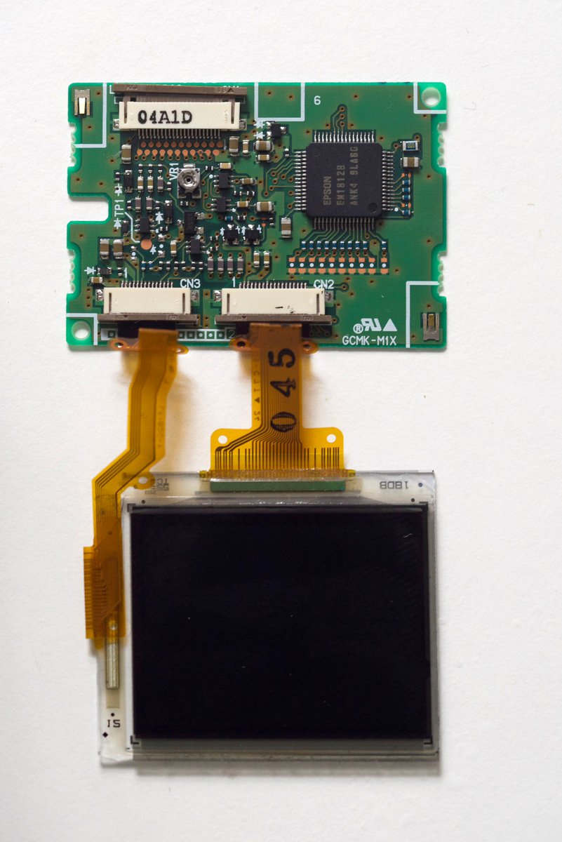
Back to the screen I got, here is it with the metal case removed. Looks like we've got a screen module with 2 COG driver LSI, and a board with one additional TCON chip and some power supply circuitry. (The screen takes one 5V rail and one -32V rail power input)
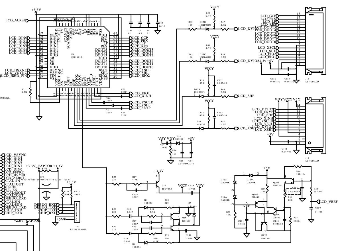
Not important, but I happen to find the schematics for that board on the screen so I am putting it here as well. Taken from Toshiba PDR-M60 camera's service manual. (This also reveals one of the real-world use of this specific screen).
So now, what does it take to drive this screen and display something with RP2040? Pinout-wise it looks like a typical DPI/ RGB interface a lot. We've got HVsync, pixel clock (called FIN here), and data lines. But upon further examination, it's not quite the same...
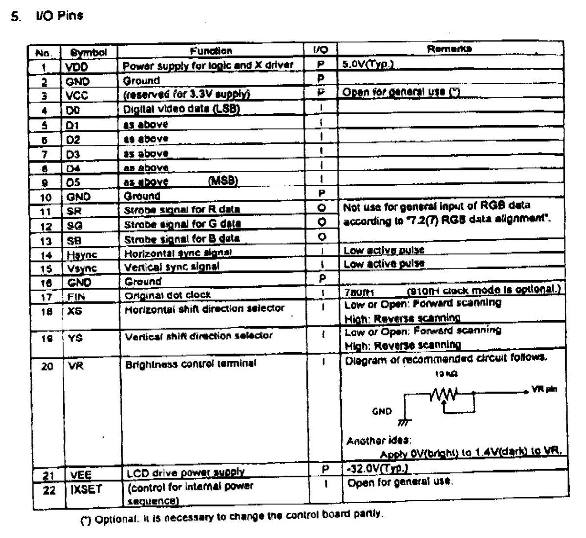
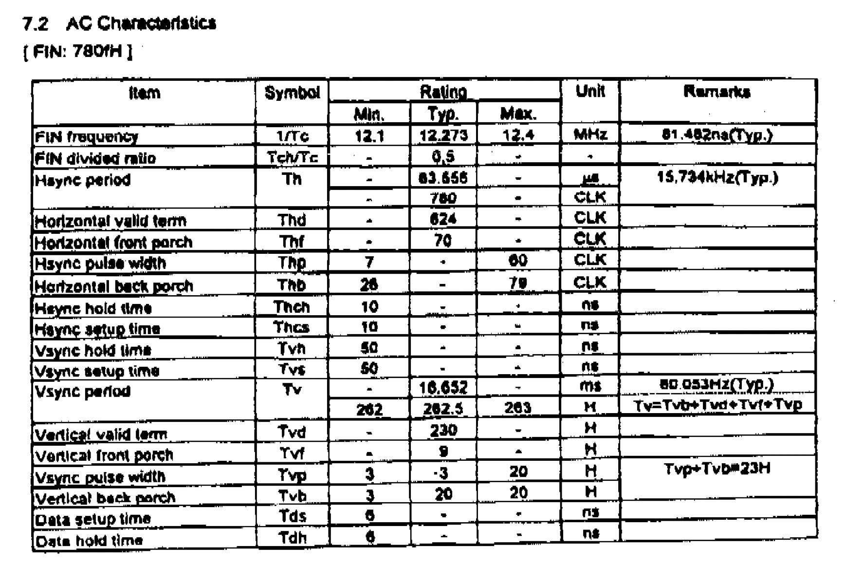
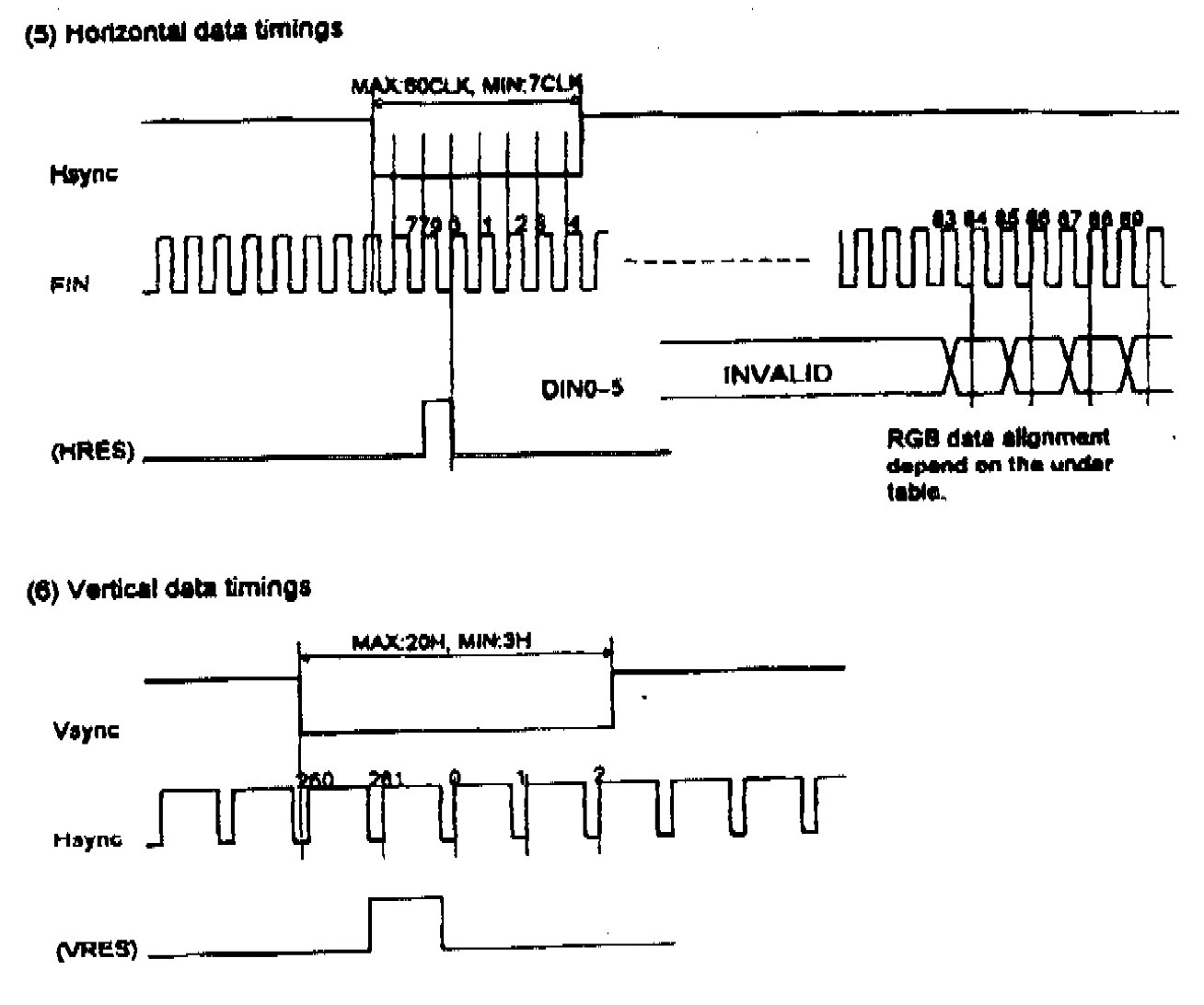
For instance, the FIN actually runs at 2X the pixel frequency (2 cycles for 1 pixel). The line length must be exactly 780 cycles otherwise it won't display anything. Field length alters between 262 lines and 263 lines in every field. Designed to display interlaced video I guess? (This tracks NTSC standard)
But these are easily solvable thanks to the great programmability of RP2040’s PIO. So as a result I got this.
Next step, go color! This also poses a bit of challenge: the screen uses RGB delta subpixel layout, instead of more commonly used RGB stripe layout. This was/ is popular on camera/ camcorder screens though. I decided to just simply map one RGB pixel to one single color subpixel.
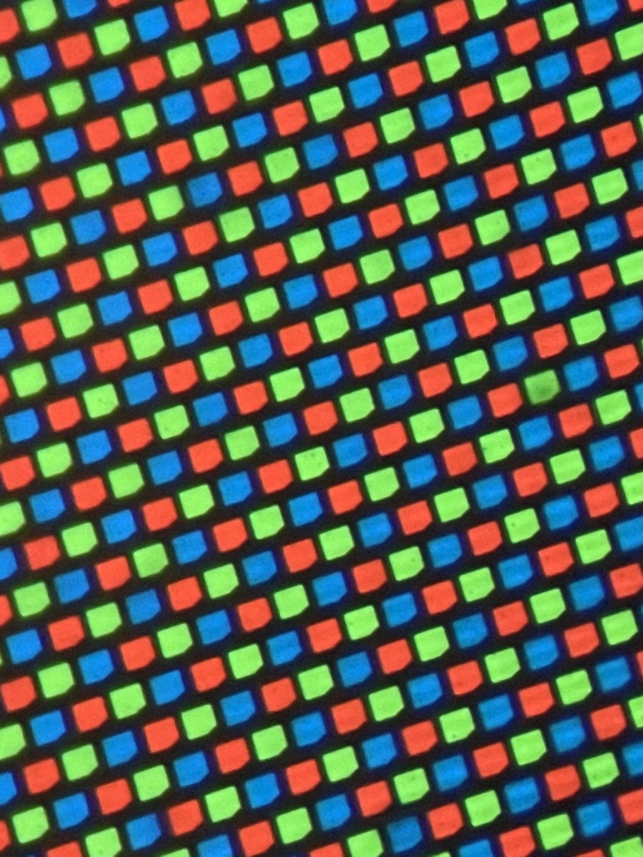
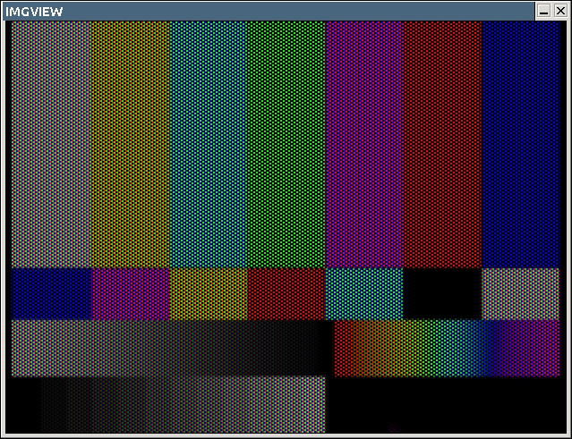
This introduces issues like aliasing, as this mapping is essentially a down-sampling process. Due to the pixels are not aligned to the square grid, I need to do some interpolation to get the image right. I am not sure what is the right thing to do but looks good. (PC simulation)
Then if I put this to the hardware... (+fixing some bugs and figuring out the pixel mapping to the screen) I got this (Pixiv ID = 85638376)
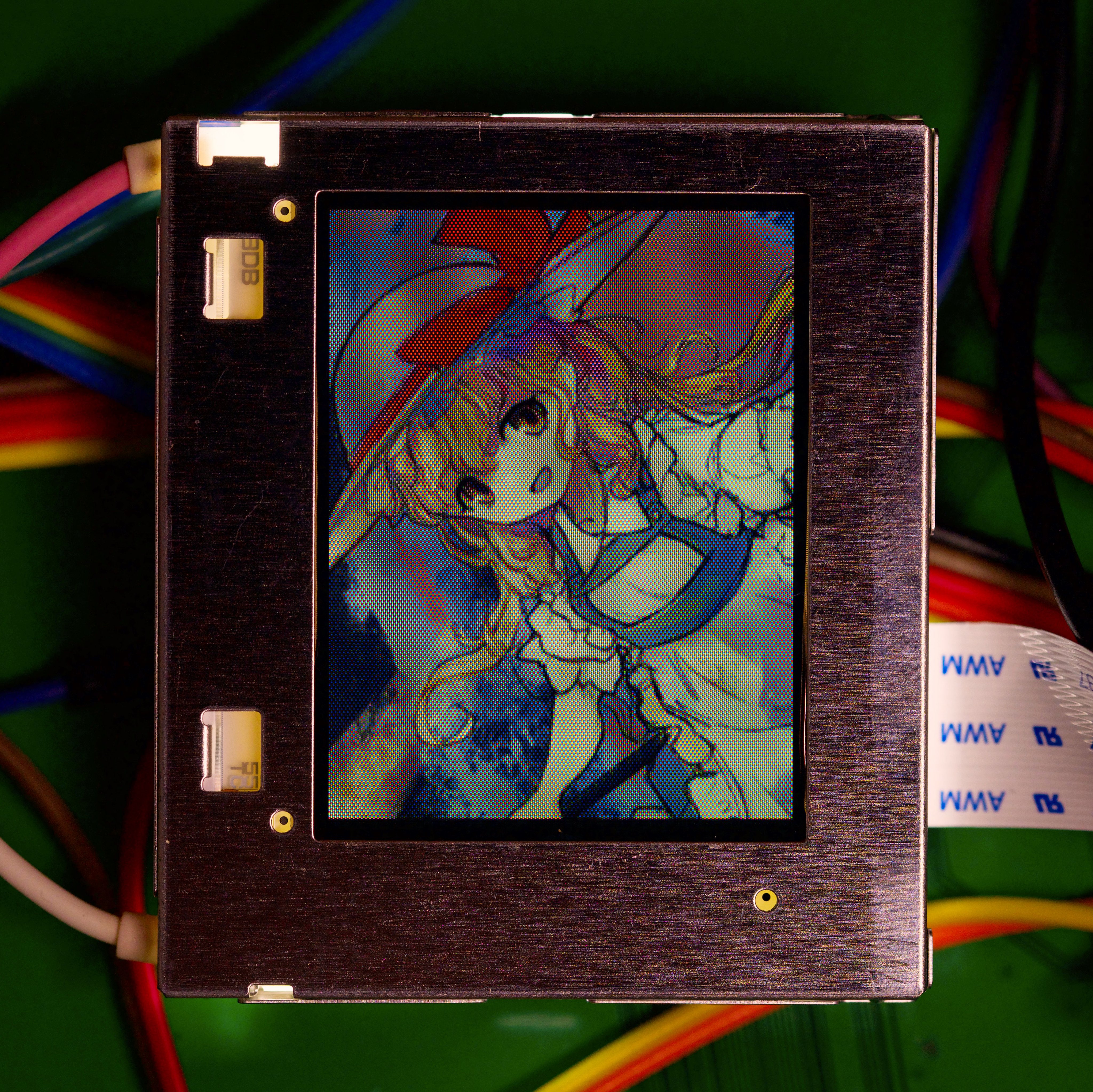
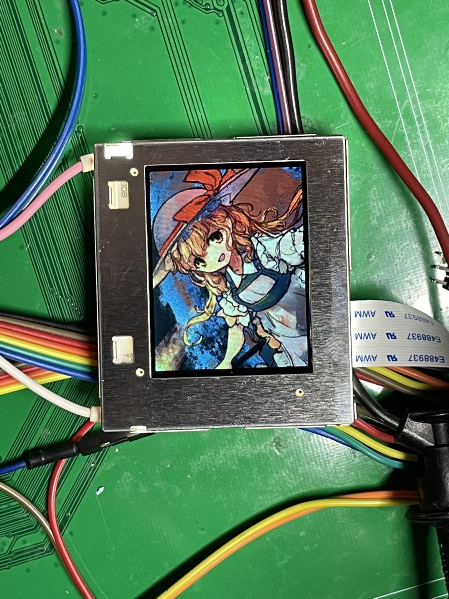
That was a high resolution shot with my camera, so you could see individual pixels. Here is the same image but shot with my phone (and 2X digital zoom), the intention is to hide/ blur the subpixel details.
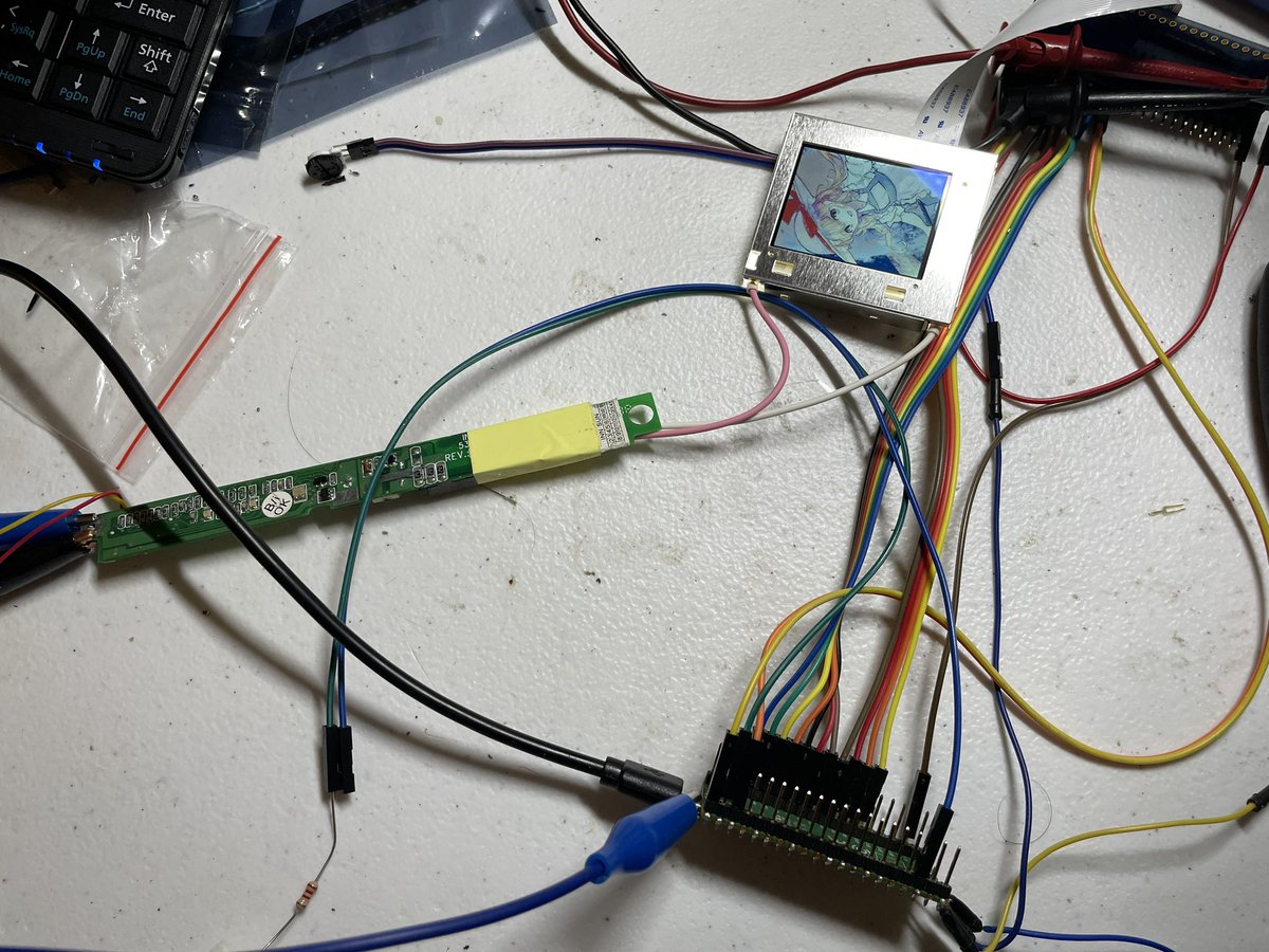
The somewhat messy setup: screen, RP pico, and a generic laptop inverter board to drive the CCFT backlight.
The source code in case you ever get your hands on some similar TFD screens or just want to take a look: https://github.com/zephray/driving-lcds/tree/main/lb18db.
That's it for today, thanks!